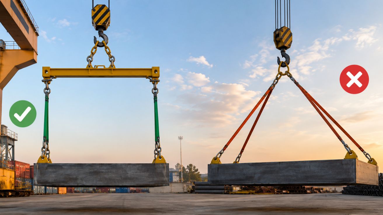

A piece of rigging equipment can carry its full rated capacity in one configuration and considerably less in another, without any change to the equipment itself. The variable responsible for this difference is sling angle, the angle formed between a lifting sling and the horizontal plane of the load. Understanding how dramatically this angle affects usable capacity is one of the more consequential pieces of practical knowledge in rigging work, precisely because the effect isn’t intuitive and the consequences of ignoring it can be severe.
Vertical Force Requirements Increase Sharply as Angles Decrease
When rigging slings run nearly vertical, close to 90 degrees relative to horizontal, the tension in each sling closely matches the actual share of the load it supports. As that angle decreases, becoming more horizontal, the tension required in each sling to support the same vertical load increases substantially, since a larger portion of each sling’s tension gets consumed overcoming the geometry of the shallower angle rather than directly supporting the load’s weight.
This relationship isn’t linear. A modest reduction in sling angle from a steep, near-vertical position produces a relatively small increase in required tension, but continuing to reduce that angle toward horizontal produces increasingly dramatic tension increases, to the point where a sling angled quite shallow relative to horizontal can require tension many times greater than the same sling positioned closer to vertical, even though it’s still lifting the exact same actual load weight.
A Component’s Rated Capacity Assumes a Specific Angle
Rigging equipment ratings, including the working load limits published for spreader beams, lift beams, and related equipment, typically specify a particular sling angle the rating assumes, commonly 45 degrees in many published specifications. This assumption matters considerably, since using that same equipment at a shallower angle than the rating assumes means the actual tension experienced by the rigging exceeds what the published rating accounted for, even though the total weight being lifted hasn’t changed at all.
This distinction explains why rigging failures sometimes occur even when the total load weight falls comfortably within a component’s stated capacity. The failure doesn’t happen because the load was too heavy in absolute terms. It happens because the actual angle used during the lift created tension exceeding what the component’s rating assumed, a genuinely different failure mode than simply exceeding a straightforward weight limit.
Multiple Attachment Points Compound the Angle Consideration
Lifting configurations using four attachment points, common in spreader frame and corner cap arrangements used for container and heavy equipment lifting, distribute load across those points in a way that depends heavily on the specific geometry involved. Published capacity figures for these multi-point configurations, such as ratings specified at a particular angle per set of four attachment points, reflect a specific assumed geometry that operators need to actually replicate in practice for that rating to remain valid.
Deviating from this assumed geometry, whether through an unusually shaped load, uneven attachment point spacing, or rigging positioned at an angle different from what the rating assumes, changes the actual load distribution across those points in ways that a simple total-weight calculation wouldn’t reveal. This is precisely why rigging equipment specifications include specific geometric assumptions alongside weight ratings, rather than publishing weight capacity alone as if geometry were irrelevant to actual safe operation.
Spreader Bars Solve This Problem by Changing the Geometry Entirely
Rather than requiring operators to carefully manage sling angle on every individual lift, spreader bars address the angle problem structurally by physically separating attachment points at a fixed distance, allowing slings connecting to the load below to run closer to vertical regardless of how far apart the actual attachment points on the load itself might be positioned. This structural approach removes much of the angle-related capacity reduction that would otherwise occur if slings ran directly from a single overhead point down to widely spaced attachment points on the load, an arrangement that would create precisely the shallow-angle geometry responsible for reduced usable capacity.
A spreader bar for rigging applications specifically addresses long, wide, or oddly proportioned loads where direct vertical lifting isn’t geometrically practical, maintaining sling angles close to vertical even when the load’s actual attachment points are spread across considerable distance, which preserves much more of the rigging’s rated capacity than a direct, unassisted lift at a shallow angle would allow.
Load Shape Determines Whether Angle Management Requires Special Equipment
Not every lift requires spreader bar geometry to maintain favorable sling angles. Compact loads with attachment points positioned relatively close together can often be lifted with slings running at a comfortably steep angle without any additional equipment. The angle problem becomes significant specifically when a load’s attachment points are widely separated relative to the available headroom for rigging above the load, a geometry common in long, narrow loads like pipe, beams, or standard shipping containers, where the attachment points sit far enough apart that direct vertical rigging would create an unfavorably shallow angle.
Understanding Geometry Prevents a Genuinely Common Rigging Error
Rigging professionals who understand how sling angle affects actual working tension, independent of a load’s total weight, make meaningfully safer equipment selection and setup decisions than those who evaluate lifts purely on total weight against a component’s published capacity. This geometric understanding explains why experienced riggers pay close attention to headroom, attachment point spacing, and the resulting sling angle before every lift, recognizing that the same load, the same equipment, and the same total weight can represent a perfectly safe lift or a dangerously overloaded one, depending entirely on the angle geometry involved in how that lift actually gets rigged.
Read More: In-House Regulatory Team vs. EU Regulatory Affairs Consultancy: Which Model Actually Saves You More?


Leave a Comment